The quality of an HDPE DWC pipe system is determined as much by how it is installed as by the quality of the pipe itself. An IS 16098-certified SN8 pipe installed in a poorly prepared trench with inadequate bedding or rushed jointing will underperform — deflecting beyond safe limits, developing joint leaks, or failing to drain at the designed hydraulic capacity. The same pipe, installed correctly and according to the specification, will deliver 50 years of maintenance-free performance underground.
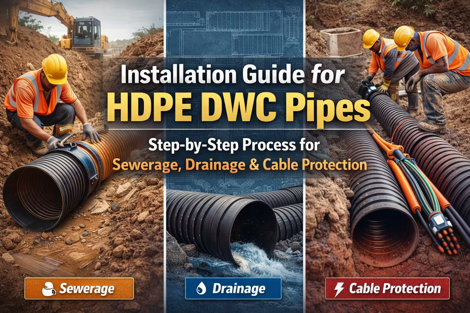
This guide covers every stage of HDPE DWC pipe installation: site preparation and planning, trench excavation, bedding, pipe laying, the two jointing methods (EPDM rubber ring and solvent/heat coupling), sidefill compaction, backfilling, testing, and post-installation checks. It is written for contractors, project engineers, and site supervisors managing sewerage, stormwater drainage, agricultural drainage, and underground cable protection projects across India — and it is aligned with the requirements of IS 16098 (Part 2): 2013 and IS 16205 Part 24: 2017, the Bureau of Indian Standards specifications that govern HDPE DWC pipe systems.
Before getting into the installation steps, it helps to understand the engineering of the pipe you are working with — because the DWC pipe’s unique dual-wall structure determines several key installation parameters.
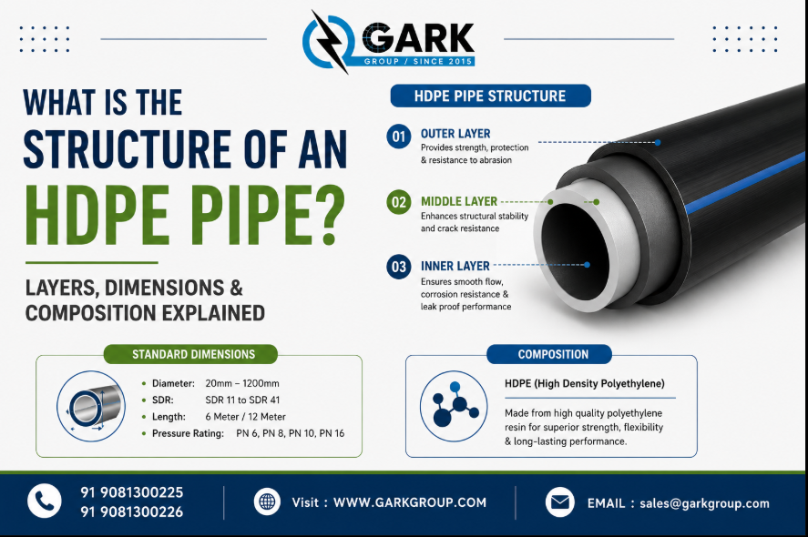
An HDPE DWC (Double Wall Corrugated) pipe has two distinct layers. The outer wall is corrugated — a wave-ribbed profile that functions structurally as a series of arches, distributing external soil loads and traffic loads uniformly around the pipe circumference rather than concentrating stress at any single point. The inner wall is smooth — providing low-friction hydraulic flow for drainage, or a clean, debris-free bore for cable conduit applications. The two layers are co-extruded simultaneously from HDPE compound and thermally fused into a single inseparable unit during manufacture.
The SN (Nominal Ring Stiffness) class of a DWC pipe — the most important structural specification — directly determines the installation parameters. Ring stiffness is measured in kN/m² and represents the pipe’s resistance to external radial deformation under load. Gark Polyplast manufactures HDPE DWC pipes to SN8 class — the highest standard infrastructure grade under IS 16098 — with a ring stiffness of 8 kN/m². SN8 pipes are rated for burial depths up to 10 metres with properly specified backfill and for installation under roads and highways subject to vehicular loading.
The critical installation consequence of the DWC pipe’s flexible structure is that it must be installed with correct embedment on all sides. Unlike rigid RCC pipes, which can bear load on their own structural body, HDPE DWC pipes rely on the pipe-soil system — the combination of the pipe’s ring stiffness and the properly compacted soil surrounding it — to achieve their rated load-bearing performance. This means bedding quality and sidefill compaction are not secondary concerns; they are primary determinants of the installed pipe’s structural performance.
For a comprehensive understanding of DWC pipe structure, material grades, SN classification, and applications, refer to our detailed technical guide What is DWC Pipe? Meaning, Structure & Applications.
Good installation starts well before the first trench is opened. The planning stage determines whether the project proceeds efficiently or encounters avoidable problems.
Before excavation begins, conduct a full site survey to establish the pipeline route, confirm the hydraulic gradient (for gravity drainage), identify existing underground utilities, and confirm access for pipe delivery vehicles and any mechanical plant needed for excavation. In urban areas, check with the relevant utility authorities (electricity distribution, gas, telecom, water) for underground service maps. Striking an existing buried utility is a serious safety incident and a project delay that proper route planning prevents entirely.
For drainage applications, confirm the overall fall of the pipeline. IS 16098 specifies that HDPE DWC pipes in non-pressure gravity drainage are installed with a minimum gradient of 1:100 (1 cm fall per metre of horizontal run) for 110mm to 200mm diameters, and not less than 1:200 for larger diameters. Insufficient gradient allows solids to settle and creates blockages; excessive gradient in soft soils can cause scouring at joints.
HDPE DWC pipes are significantly lighter than equivalent concrete or ceramic pipes — a 6-metre length of 110mm DWC pipe weighs approximately 6–8 kg, and a 315mm pipe approximately 55–65 kg — but they still require careful handling to prevent damage before installation. Specific requirements:
Pipes must be stored on flat ground, not on gravel or sharp material that could dent or scratch the outer corrugated surface. Stack pipes horizontally, no more than 3 metres high, with sockets at alternating ends to distribute weight evenly. For coiled pipe (available in 50m or 100m coils for 40mm–110mm OD), store coils flat and do not allow them to stand vertically — the HDPE will deform under its own weight over time. Do not drop pipes or allow them to roll against sharp edges. While HDPE is impact-resistant, repeated impact loading from rough handling can initiate micro-cracks in the outer corrugations that are invisible at delivery but become failure points after burial. Inspect each pipe length and coupling before use — reject any piece showing visible cracks, deformation, or joint damage.
Trench geometry is the foundation of a correctly installed pipe system. IS 16098 (Part 2) specifies trench dimensions as a function of pipe outer diameter.
The minimum trench width at the pipe invert level must allow for adequate compaction of sidefill material on each side of the pipe barrel. The rule is: minimum 150mm clear space on each side of the pipe outer diameter, plus the pipe diameter itself. In practice, for IS 16098 compliance:
For pipes up to 200mm OD: minimum trench width = pipe OD + 300mm (150mm each side) For pipes 200mm to 400mm OD: minimum trench width = pipe OD + 400mm (200mm each side) For pipes above 400mm OD: trench width per project-specific design, typically OD + 500mm minimum
Excessively narrow trenches prevent adequate compaction of the sidefill material against the pipe haunches — the critical zone where compaction most directly supports the pipe’s ring stiffness performance. Excessively wide trenches increase excavation volume and soil replacement cost without engineering benefit; they can also increase the total prism load on the pipe from a wider column of settled backfill.
Trench depth is the sum of the required cover depth above the pipe crown plus the pipe outer diameter plus the bedding layer thickness. The minimum cover requirement depends on the application and loading conditions:
Under unpaved areas and agricultural land: minimum 600mm cover above the pipe crown Under roads carrying light traffic (district roads, farm tracks): minimum 800mm cover above the pipe crown.
Under highways, expressways, and heavy commercial vehicle routes: minimum 1,000mm cover above the pipe crown, with SN8 specification mandatory Under railway tracks: minimum 1,500mm cover, project-specific engineering design required.
For SN8 HDPE DWC pipe, the maximum burial depth with properly specified granular backfill is 10 metres. This considerable burial capacity is one of the product’s key engineering advantages over lighter-duty alternatives.
The trench bottom must be firm, stable, and free of loose material, protruding stones, tree roots, and organic matter. In soft soil conditions — common in alluvial plains, paddy field areas, or coastal zones — overexcavate by 150–200mm and replace the excavated material with compacted granular fill before placing the bedding layer. In rock conditions, overexcavate by a minimum of 150mm below the required invert level to allow adequate bedding depth; rock points must not be in direct contact with the pipe barrel.
The bedding layer is where the most common installation errors occur — and where those errors have the most significant consequences for long-term pipe performance. The bedding layer simultaneously provides stable, uniform support for the pipe, distributes load from the pipe into the trench foundation, and establishes the precise gradient at which the pipe will drain.
Use clean, angular, well-graded granular material with the following characteristics:
Maximum particle size: 20mm for pipes up to 315mm OD; no particles exceeding one-third of the pipe annular space Gradation: well-graded (not uniformly graded, which allows inter-particle movement); coarser particles should be angular not rounded for compaction stability Fines content: maximum 5% fines passing 75-micron sieve to allow drainage through the bedding and prevent migration of fines into the pipe invert Suitable materials: coarse sharp sand, crushed stone aggregate, pea gravel conforming to IS 383.
.
Do not use soft clay, organic soil, silty material, or any excavated material containing clods larger than 50mm as bedding. Do not use material containing debris, construction waste, or chemically aggressive content.
Place the bedding layer to a compacted thickness of 100–150mm for pipes up to 315mm OD. For larger diameters and in soft soil conditions, a 150–200mm bedding thickness provides more stable support. Level and compact the bedding using a plate compactor or hand tamper — do not compact directly over the pipe position, as you will be cutting the invert channel into the compacted surface.
Once the bedding is placed and compacted to the required level, cut a slight invert channel at the correct gradient that matches the pipe socket profile — this allows the pipe barrel to bear on the bedding uniformly around its lower 120° arc while the socket sits in a slightly wider cut-out that does not create a stress concentration at the joint location. This channel cutting is the precise equivalent of the bedding shaping required for RCC pipes, but it is simpler to execute because the HDPE DWC pipe’s corrugated outer surface provides natural mechanical interlock with the granular bedding.
With the trench prepared and bedding placed, the pipe laying sequence begins.
Always lay HDPE DWC pipes starting from the downstream end and working upstream — in the direction against the flow. This ensures that each spigot (plain end) is pushed into the socket of the previously laid pipe in the direction of flow, which is the correct joint orientation for drainage applications. If pipes were laid from upstream to downstream, the socket openings would face upstream and could allow sediment-laden flow to enter the joint gap.
For smaller diameters (up to 200mm), pipes can be lowered by hand using guide ropes — do not push or drop pipes down the trench wall. For larger diameters (above 200mm OD in 6m lengths), use a sling or strap (not chains or steel cables that can damage the pipe surface) and a mechanical excavator or crane to lower the pipe carefully. The lifting sling should contact the pipe on the corrugation profile, not at the socket ends.
Check the pipe gradient at each length laid using a spirit level, laser level, or traveller board referenced to boning rods. A gradient error accumulates over a pipeline run: a 2mm error per 6m pipe length creates a 100mm total error over a 300m run — enough to create standing water points and solids deposition in the drainage line. Check gradient frequently; correct deviations by adjusting the bedding before the sidefill is placed.
Correct jointing is one of the most operationally significant steps in HDPE DWC pipe installation. DWC pipes use two primary jointing methods depending on the application:
The rubber ring joint is the standard jointing method for IS 16098 HDPE DWC pipes in sewerage and drainage applications. Each pipe length has an integrated in-line socket (bell end) at one end — formed during manufacture by expanding the corrugated profile into a socket shape — containing a pre-fitted EPDM (Ethylene Propylene Diene Monomer) rubber ring seated in the corrugation valley.
Jointing procedure:
Inspect the rubber ring for cleanliness, correct seating, and absence of twists or gaps. A rubber ring with a single gap or twist will allow infiltration/exfiltration at operating pressure. Clean the spigot end (plain end) of the next pipe with a dry cloth to remove soil, moisture, or debris.
Apply the specified pipe lubricant — use only the manufacturer-approved soap-based lubricant or a lubrication cream compatible with EPDM rubber. Never use oil-based lubricants, petroleum grease, or solvent-based substances, as these degrade the EPDM ring and cause joint failure. Apply lubricant to the spigot end and also lightly to the rubber ring inner face.
Align the spigot end squarely with the socket mouth — the pipe ends must be coaxially aligned, not at an angle. Push the spigot into the socket firmly until the spigot insertion mark (factory-marked on the pipe) is flush with the socket rim. For pipes up to 160mm, hand pressure and body weight against the spigot end is typically sufficient. For pipes 200mm and above, use a timber push block (to distribute load across the full end face without point loading the pipe) against the spigot end and lever the pipe home using a timber batten pivoted on the trench wall or the previously laid pipe.
After insertion, pull the pipe back by 10–15mm to allow for thermal contraction of the HDPE in cold weather conditions — this prevents joint pullout from subsequent temperature-driven pipe shortening. This “draw-back” step is important in areas with large day-night temperature variation.
Verify joint engagement by marking the insertion depth on the spigot before jointing and confirming the mark position relative to the socket rim after assembly.
When a pipe length must be field-cut — to fit the end of a run, accommodate a change in direction, or repair a section — the cut end does not have an integrated socket. In this case, a mechanical coupler (an external sleeve fitting that engages the corrugation profile on both pipe ends) or a field-formed socket coupling is used.
For drainage applications in confined spaces, purpose-designed HDPE coupler fittings — conforming to IS 16098 and fitted with EPDM rings on both internal engagement faces — provide a water-tight field joint. For cable conduit applications where watertightness is secondary to ease of installation, corrugated mechanical couplers provide adequate joint stability.
Cutting HDPE DWC pipe in the field: Use a fine-toothed handsaw or mechanical pipe cutter — not a cold chisel or angle grinder disc that produces heat-deformed cut edges. Cut squarely perpendicular to the pipe axis; an angled cut prevents proper coupler engagement and creates a leak point. After cutting, chamfer the cut edge with a pipe reamer or rough file to remove the sharp burr and create the entry angle needed for coupler insertion.
HDPE DWC pipe systems are not installed as single straight runs — they connect to manholes, change direction at bends, accept lateral connections from branch drains, and terminate at outfalls. Each of these transition points requires specific fittings.
IS 16098-conforming HDPE DWC fittings are manufactured from the same HDPE compound as the pipe, with identical chemical and structural properties. They include: 45° and 90° bends for direction changes, tee junctions for lateral connections, reducers for diameter changes, end caps for closed ends, manhole connectors for transition to precast concrete or HDPE manhole chambers, and saddle connections for branch tie-ins on existing pipes.
At manholes and inspection chambers, use purpose-manufactured HDPE transition fittings with built-in gaskets to connect the DWC pipe to the chamber wall. Never cut a rough hole in the chamber wall and mortar the pipe in directly — mortar bonds incompatibly with HDPE’s smooth outer surface, and thermal movement of the HDPE pipe relative to the rigid concrete chamber will open the joint gap within a few seasonal cycles.
The embedment zone — from the trench bottom to 300mm above the pipe crown — is the most structurally important backfill zone and requires the highest attention to material quality and compaction technique.
Use the same granular material specified for bedding (clean angular aggregate, maximum 20mm particle size, maximum 5% fines) for the sidefill zone. Place the sidefill in layers of 150mm maximum uncompacted thickness on both sides of the pipe simultaneously — do not fill one side and then the other, as this creates unequal lateral pressure and can cause the pipe to shift from its set alignment and gradient.
Compact each 150mm layer using a hand-operated plate compactor or hand tamper in the area directly beside and under the pipe haunches. The haunching zone — from the pipe invert up to the pipe centreline level — is the most critical compaction zone. Inadequate haunching is the most common cause of post-installation pipe deflection, as it allows the pipe to flatten slightly under vertical soil load. Aim for 90–95% Standard Proctor Density in the haunching zone.
Do not use heavy vibratory roller compactors in the embedment zone within 1 metre of the pipe — the dynamic impact loading from heavy plant will damage the pipe structure. Hand tampers and light plate compactors (up to 60kg operating weight) are the correct tools in this zone.
Continue the granular sidefill and compaction up to 300mm above the pipe crown. Above this level, compaction requirements are less critical and native soil or site-won material (free of clods, organic matter, or particles exceeding 50mm) can be used for the main backfill.
Above the 300mm over-crown embedment zone, backfill can proceed with either site-won material (free of clods larger than 50mm, organic matter, or construction debris) or imported fill. Place in layers not exceeding 300mm uncompacted thickness and compact each layer with mechanical equipment appropriate to the depth of cover above the pipe.
Under roads and trafficked surfaces, ensure the upper backfill meets the compaction requirements of the relevant road authority — typically 95% Standard Proctor Density or equivalent. Under agricultural land, normal field compaction to match surrounding ground density is sufficient; excessive compaction under agricultural land creates drainage-impedance layers.
The standard warning tape — typically yellow for drainage/sewerage or orange for cable conduits, with printed identification text — must be laid approximately 300mm above the pipe crown before the final layers of backfill. This tape alerts future excavation works to the buried service below.
Before backfill is completed and the site is reinstated, the installed pipeline must be tested to confirm joint integrity and alignment.
For IS 16098 sewerage systems where watertight joints are specified, a low-pressure air test is the standard acceptance test in India. The test pressurises the pipe section between two plugged ends to 50 mbar (5 kN/m²) and monitors pressure over a minimum hold period of 5 minutes. A pressure drop of less than 5 mbar over 5 minutes confirms acceptable joint integrity. Any section failing the air test must be excavated to locate the leaking joint, corrected, and retested.
A mandrel — a rigid cylindrical tool sized at 95% of the pipe’s nominal inner diameter — is pulled through the installed pipe section to verify that the pipe has not deformed beyond acceptable limits during installation and initial soil loading. If the mandrel passes freely through the full pipe run, ring deflection is within the IS 16098 specification limit of 5% maximum. A mandrel that binds indicates excessive deflection at a specific location, requiring excavation, diagnosis of the cause (typically inadequate haunching or point loading from a hard object in the sidefill), and correction.
For municipal sewerage projects, post-installation CCTV inspection of the installed pipe interior is increasingly specified by Indian municipal corporations and project authorities. A small wheeled camera system travels through the installed pipe and records video of the joint condition, alignment, gradient, and any structural defects. CCTV inspection provides permanent documentation of the installed system condition at handover.
After the pipeline has passed acceptance testing, reinstate the trench to the required surface condition. Under roads, ensure road base and wearing course reinstatement to the road authority’s specification. Under agricultural land, restore topsoil to its original depth and looseness. Mark the pipeline route on the as-built drawings with chainage references, manhole locations, and invert levels.
Update project records with: pipe specification (manufacturer, batch number, SN class, IS 16098 certification reference), trench dimensions, bedding and sidefill material type, test results, and date of installation. This documentation is the traceability record that enables efficient maintenance, future connection works, and system rehabilitation decisions over the pipeline’s 50-year service life.
In areas with a high water table — common in Gujarat’s coastal belt, paddy field zones, and riverine plains — the trench may be subject to groundwater ingress during excavation. Key considerations: maintain continuous dewatering during pipe laying and jointing to prevent water from floating a partially installed pipe section, which will destroy the gradient. Ensure the bedding layer is not washed out by dewatering pump discharge within the trench. In extreme cases, use geotextile fabric along the trench walls to prevent migration of fines from the native soil into the granular bedding layer.
Where a DWC pipeline must cross an existing road without open-cut trench excavation, horizontal directional boring (HDB) or pipe jacking methods are used. For HDPE DWC pipes in bore and jack applications, the pipe must be rated for the tensile pulling force applied during installation in addition to its SN rating. Consult Gark Polyplast’s technical team for guidance on pipe specification for trenchless applications — the HDPE DWC Pipes product page provides starting point specifications.
For DWC pipes installed as cable conduit under IS 16205, the installation procedure follows the same trench, bedding, jointing, and backfill sequence as drainage applications, with two additional requirements. First, pull ropes or cable draw tapes must be installed in the pipe as it is laid, to enable cable pulling without excavation after backfill.
Second, for multi-duct installations, spacer clips must be used to maintain the designed spacing between adjacent conduits and prevent them from shifting during backfill compaction. For telecom OFC applications requiring pre-lubricated duct bore, Gark Polyplast’s PLB Duct Pipes provide the permanently lubricated internal surface required for high-speed cable blowing installations.
Understanding the most frequent field errors prevents the most common post-installation failures:
Using native excavated soil as bedding material is the most prevalent mistake on Indian infrastructure sites. Clay, silt, and organic soil cannot be compacted to the density required to support the pipe-soil system. The result is progressive settlement and deflection. Always use specified granular material.
Skipping or under-doing haunching compaction — the area beneath the pipe haunches on each side of the invert — is the most structurally significant error. Voids beneath the haunches allow the pipe to flatten under vertical load regardless of the SN class. Hand compact the haunching zone meticulously before proceeding.
Joining pipes with the socket facing the wrong direction — sockets facing upstream — allows sediment and sewage to enter the joint gap, progressively degrading the rubber ring and creating a leak. Always lay from downstream to upstream.
Applying incorrect lubricant to rubber ring joints — oil-based or petroleum-based products — degrades EPDM rubber over months to a condition where the ring loses its sealing compression. Use only soap-based or manufacturer-approved lubricant.
Not performing the air test before reinstatement leaves joint leaks permanently buried, where they create soil erosion around the pipe and progressive trench settlement that damages surface infrastructure above.
Gark Polyplast Pvt. Ltd. manufactures HDPE DWC Pipes at its ISO 9001:2015, ISO 14001:2015, and ISO 45001:2018 certified facility in Palanpur, Gujarat, to IS 16098 (Part 2): 2013 and IS 16205 Part 24: 2017 with BIS/ISI mark certification.
Key product parameters:
Material: Virgin-grade HDPE compound — black outer with blue, green, or orange inner bore (custom inner colours available for colour-coded cable conduit projects) Outer diameter range: 40mm to 315mm OD (as per IS 16205 Part 24) Ring stiffness class: SN8 (8 kN/m²) — the highest infrastructure-grade classification Available lengths: 6m lengths (standard); 50m and 100m coils for smaller diameters Standard compliance: IS 16098 (Part 2): 2013 and IS 16205 Part 24: 2017 with BIS/ISI mark Maximum burial depth: 10 metres with properly specified granular backfill In-house quality testing: Ring stiffness, impact resistance, ring flexibility, elongation at break — tested per IS 16098 and IS 16205 before release.
For complete dimensional tables, weight per metre, and SN class specifications, download our product catalogue. For project-specific diameter selection, SN class verification, or trenchless application guidance, contact our technical team.
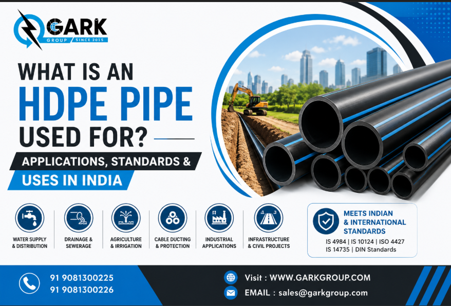
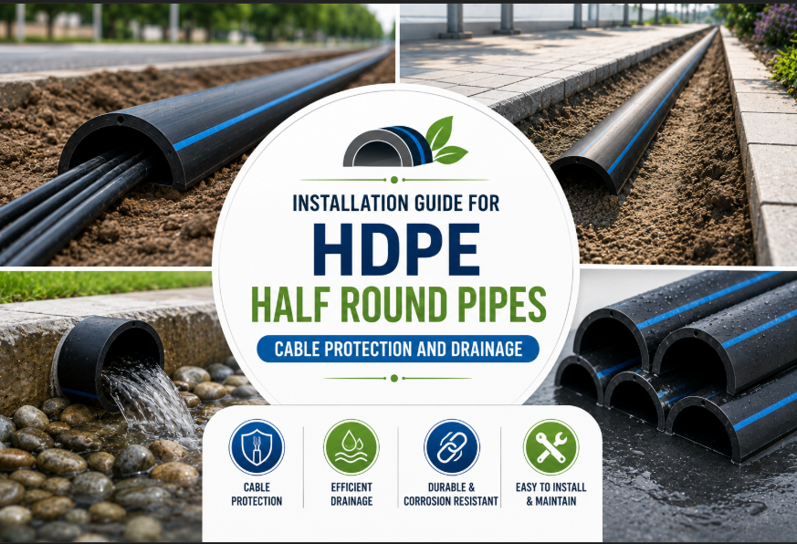
For split DWC pipes used in cable retrofit protection applications (installing over live cables without disconnection), our DWC Half Round Pipes and HDPE Half Round Pipes provide the purpose-designed solution. For HDPE pressure pipe installation guidance and SDR selection, our technical guides, What is SDR in HDPE Pipes? and What is an HDPE Pipe? Uses, Benefits and Applications in India provide the relevant technical framework.
Use clean, angular, well-graded granular material with a maximum particle size of 20mm and no more than 5% fines. Coarse sharp sand, crushed stone aggregate, or pea gravel conforming to IS 383 are the standard specified bedding materials. Do not use site-won clay, silt, organic soil, or any material containing particles larger than 50mm. The bedding layer should be placed to a compacted thickness of 100–150mm and levelled at the correct gradient before pipe laying begins.
The minimum cover above the pipe crown depends on the surface loading condition: 600mm under unpaved and agricultural land, 800mm under light traffic roads, and 1,000mm minimum under highways. The maximum burial depth for Gark Polyplast SN8 HDPE DWC pipes with properly specified granular backfill is 10 metres. At depths beyond this, consult the manufacturer’s technical team for project-specific structural design.
The standard field joint for IS 16098 HDPE DWC pipes uses the integrated in-line socket with a pre-fitted EPDM rubber ring. The procedure is: inspect and clean both pipe ends, apply manufacturer-approved soap-based lubricant to the spigot end and rubber ring, align the spigot coaxially with the socket mouth, push firmly home until the insertion mark on the spigot is flush with the socket rim, then draw back 10–15mm to allow for thermal contraction. Use a timber push block and lever for diameters 200mm and above.
Use only manufacturer-approved soap-based lubricants or specific EPDM-compatible lubricating creams. Never use petroleum-based grease, engine oil, or any solvent-containing lubricant — these cause progressive degradation of the EPDM rubber ring, leading to loss of sealing compression and joint failure within months of installation. The correct lubricant is typically supplied with the pipe consignment or available separately from the manufacturer.
Yes — HDPE DWC pipe can be field-cut to any required length using a fine-toothed handsaw or mechanical pipe cutter. Cut squarely, perpendicular to the pipe axis. After cutting, chamfer the cut edge with a file or pipe reamer to remove the sharp burr and create the correct entry chamfer for the coupler fitting. Do not use angle grinder discs or heat-generating cutting methods that deform the HDPE at the cut edge.
IS 16098 permits a maximum ring deflection of 5% of the pipe’s nominal inner diameter after installation. A mandrel test — pulling a rigid tool sized at 95% of the nominal inner diameter through the installed pipe section — is the standard field verification method. If the mandrel passes freely, deflection is within limits. If it binds, the affected section must be excavated, the cause identified (typically inadequate haunching), and the installation corrected before the trench is backfilled.
For non-pressure gravity drainage under IS 16098, the minimum recommended gradient is 1:100 (1cm fall per metre of run) for pipe diameters 110mm to 200mm. For larger diameters (above 200mm), 1:200 is acceptable where topographic constraints limit available gradient. Avoid gradients less than 1:200 for all sizes, as inadequate self-cleaning velocity allows solids deposition and progressive blockage. For cable conduit applications under IS 16205, gradient is less critical — provide a slight fall (minimum 1:500) towards manholes or access chambers to allow drainage of any water that enters the conduit system.
IS 16098 (Part 2): 2013 governs HDPE DWC pipes for non-pressure underground drainage and sewerage — municipal sewers, stormwater drains, agricultural drainage. IS 16205 Part 24: 2017 governs DWC pipes specifically designed for telecom and electrical cable conduit applications, defining dimensions for duct sizes from 40/33mm through 315/275mm. The pipes are structurally similar, but IS 16205 pipes are specified with colour-coded inner walls (orange for power, blue for telecom, green for general purpose) to enable identification after burial. Both standards require SN8 ring stiffness for infrastructure-grade applications.
HDPE DWC pipe installation is a systematic process where each step builds on the previous one — trench geometry determines bedding quality, bedding quality determines gradient accuracy and pipe support, jointing technique determines joint integrity, and sidefill compaction determines long-term structural performance. Shortcuts at any stage create problems that surface months or years after installation, when excavation to repair them is expensive and disruptive.
The IS 16098 and IS 16205 installation standards are not bureaucratic requirements. They are distilled engineering wisdom from decades of HDPE pipe system performance data, codified to ensure that every installed system delivers the 50-year service life that makes HDPE DWC pipe the sound economic choice over concrete and ceramic alternatives.
Gark Polyplast Pvt. Ltd. is Gujarat’s BIS/ISI certified, ISO 9001:2015, ISO 14001:2015, and ISO 45001:2018 certified manufacturer of IS 16098 and IS 16205 HDPE DWC Pipes in SN8 class, operating from Palanpur, Gujarat, with pan-India supply capability.
Explore our DWC Pipe range · Download our product catalogue · Contact us for technical guidance and project quotations · Become a distribution partner
Gark Polyplast Pvt. Ltd. is an ISI certified, BIS-marked manufacturer of HDPE DWC Pipes, HDPE Pipes, and PLB Ducts — operating from our state-of-the-art facility in Palanpur, Gujarat, since 2015.
 +91 9081300225 | +91 9081300226
 Sales@garkgroup.com | garkpolyplast@gmail.com
 www.garkgroup.com
 Gark Industrial Park, Kotda-Pirojpura Road, Palanpur, Gujarat 385010
Latest Post
Stay Updated With Insight
Subscribe to our social media channels, never miss the latest articles, expert blogs, your business effectively.
Related Post
Continue Reading
Table of Contents
×